Category: Articles

Home / Category: Articles

In the quest to have the best shack I can have, I started the implementation of CMC chokes to mitigate noise in the transmission lines. I watched a lot of videos, read some blogs, and decided these basic objectives.

  • Use a Type-31 toroid for HF operations. General knowledge indicates it’s good for 0-300MHz.
  • Enclose in a watertight box with SO-239’s on each end to simplify most aspects of insertion into existing feedlines.
  • Use as high a quality coax as I have on hand (in this case some RG8x).

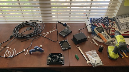
The choke was constructed to goal, and looks like this:

Type 31 Common Mode Choke using RG8x coax and ferrite toroid (mix 31)

Testing the CMC in the real world, did more harm than good to the performance of my OCF80 wire antenna. The choke was places at the end of a 70′ RG58 feed, which passes through an Armitron RCS-4 switch, to 50′ of ABR RG8 to the house passthrough wall plate. From that plate to shack is 35′ of M&P Airborne 10.

After construction, I tested the box with my AA-35 and saw a less than impressive SWR impact with a 100w dummy load attached direct to the choke box.

CMC SWR chart

In the real world, the insertion of the choke had the following impact on 20m performance of the OCF80.

RG8 -> RCS-4 -> MP7 Flex -> CMC -> RG58 Feed -> OCF80SWR: 2.6 : 1
RG8 -> RCS-4 -> RG58 Feed -> OCF80SWR: 1.8 : 1
RG8 -> RG58 Feed -> OCF80SWR: 1.8 : 1

I was able to verify that the RCS-4 switch was not a factor in the SWR difference. The M&P 7 Ultraflex is a 6′ jumper between RCS-4 and the CMC box. I don’t suspect that, as it tests flat SWR into a dummy load.

Dumping all the graphs off of the AA-35, I see a very interesting patterns in the charts.

CMC-31 Phase Chart
CMC-31 Z=R+jx
CMC-31 Z=RII+jX

CMC-31 Smith Chart

What is the question?

What did I do wrong here? Did I do something wrong?

I realize that all of the examples I looked at, used RG58 coax. Although the impedance is the same in the RG8x, perhaps the overall diameter, or shield type (it looks like it’s aluminum… grr) makes the suggested 12 turn construction incorrect.

Could and issue be in the way the toroid was wrapped? Most example are a simple circular wrap, but 1 example had a cross-over run at the 6 turn mark (making the 7th turn) that switches to opposite side of toroid, this making the 12th turn exist 180 degrees away from ‘insert’ point, instead of existing near insert point seen on a lot of other constructions.

I’ll probably take this one apart, wide another toroid I have with RG58 with not using the crossover, and see if that works better / different or worse.

I’m open to thoughts, ideas, corrections on this first attempt to build a choke.
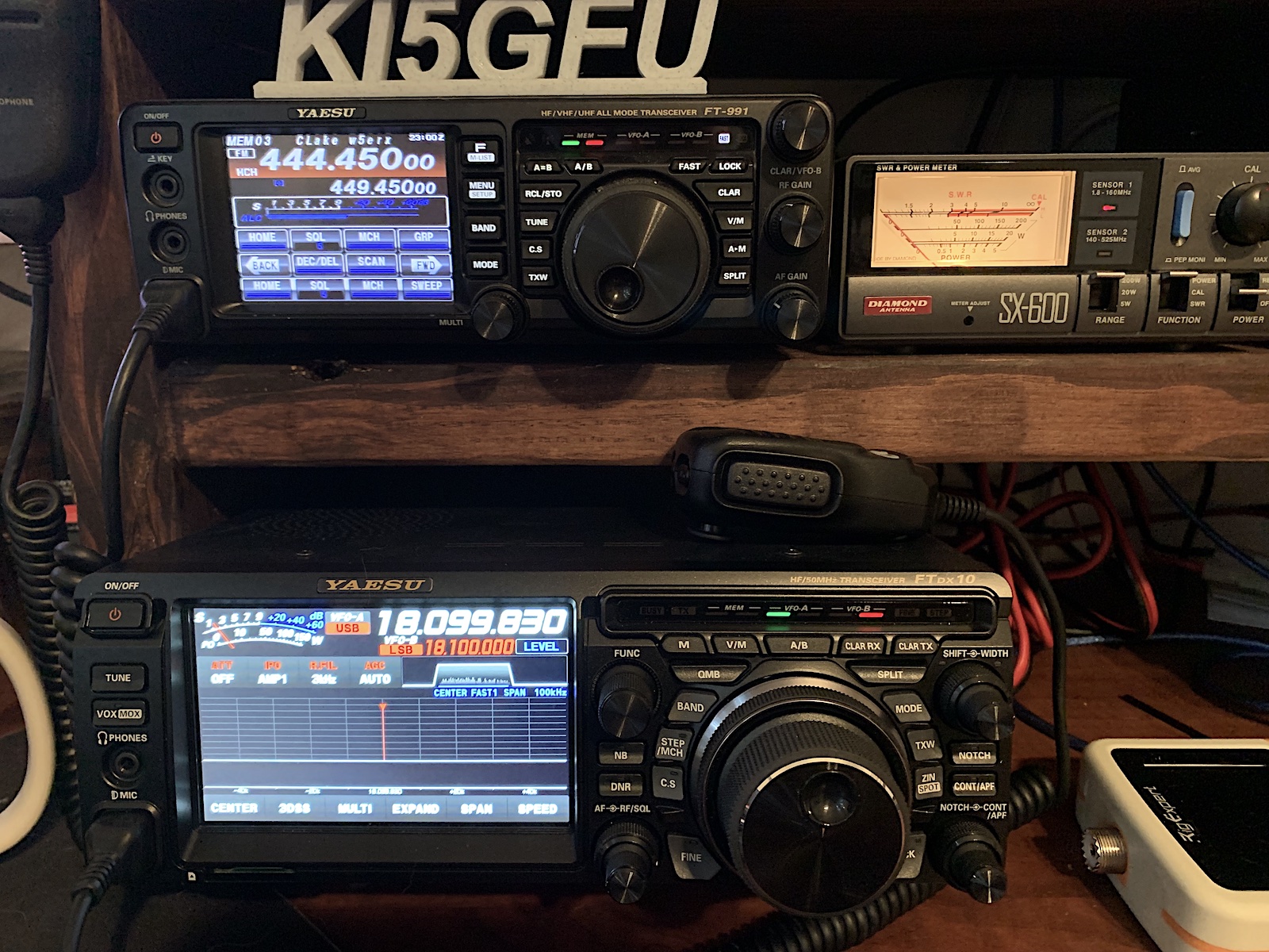
Thanks to the installation of the Ameritron RCS-4 remote antenna switcher, it’s become much easier to compare my two HF antenna installations. With a flick of the rotator, it’s easy determine which antenna is the ‘loudest’ and which is tuning up to a lower final SWR.

The Antennas

G5RV

Mounted roughly 20′ in the air (trees don’t really get tall in Texas Hill Country), with a horizontal ‘L’ configuration, with 1 leg running N-S, and another ENE-SSW. This is fed entirely with repurposed RG6 satellite coax, through the remote switch box outside the house, and another 60′ run from the remote switcher to the ladder line.

Offset Fed Window 80 (OCF80)

Mounted roughly 20′ in the air, with an almost perfect N-S orientation, with the long let on the South side of the run. This fed with a mix of RG6 (shack to antenna switch), and 100′ of cheap RG58 from switcher to the feed elevated feed point in a tree.

RCS-4 Remote Coax Switcher

AMERITRON RCS-4 remote switch mounted and grounded outside shack/house.

Audible – which is the ‘loudest’

This was easy.. flipping back and forth between the G5RV and the OCF80 across various bands showed that the G5RV, was the loudest by roughly double (3db.. give or take). It’s quite obvious both to the ear, and to the scope which was the winner here.

Resonance – which is the most favorable

This is where it got interesting. Using the trusty RigExpert AA-35, I ran scans of both antennas from the shack side coax switch feed (through the switcher).

Ameritron RCS-4 Remote Coax Switch

The results sort of conflicted with my observations regarding which antenna seemed to be working better. I downloaded the scans from the RE and superimposed the two on a chart showing the HAM HF bands:

The OCF80 clearly (at least to me) seems to be markedly better in SWR, especially where it counts, in the grey HF bands. I was surprised to see the OFC80 is (or should be) a little better on 160m than the full-size 160m G5RV. The resonance is shifted to right (high) of most of the bands for the OCF80, and the opposite for the G5RV. I’ve done all I can to lengthen the OCF’s legs to shift the resonance lower, but it’s still not ‘right’.

This chart also explains why I’ve struggled with 80m as of late.. tuning is way off there. 60m is also a mess, but I’ve not tried to work 60 yet, so it’s not been an issue. But I’d like to see much better matching.

Considering that the RG6 most likely is a factor here in the shift and overall SWR, now that I’ve gotten hooked on HF, and gave upgraded radios, time to invest in proper coax. In the next week I’ll be ordering some, once I figure out how much I actually need! Another helpful feature in the RigExpert software is an analysis of the coax, including what I’m guessing is a pretty decent calculation of overall length. If this is right, I think a 500′ roll should get me from the office/shack to the switcher and out to the two antennas, retiring all the RG6.

More to come!

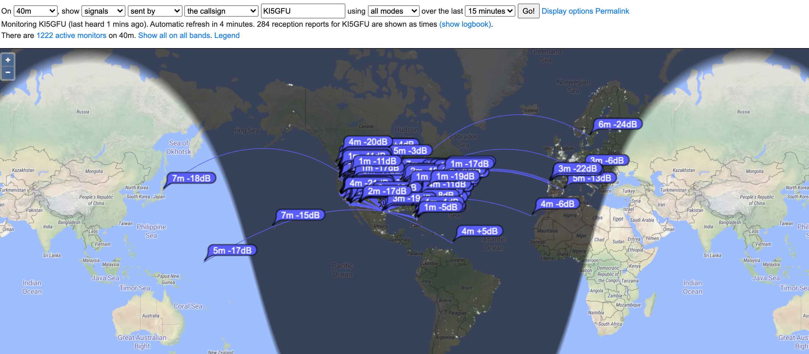
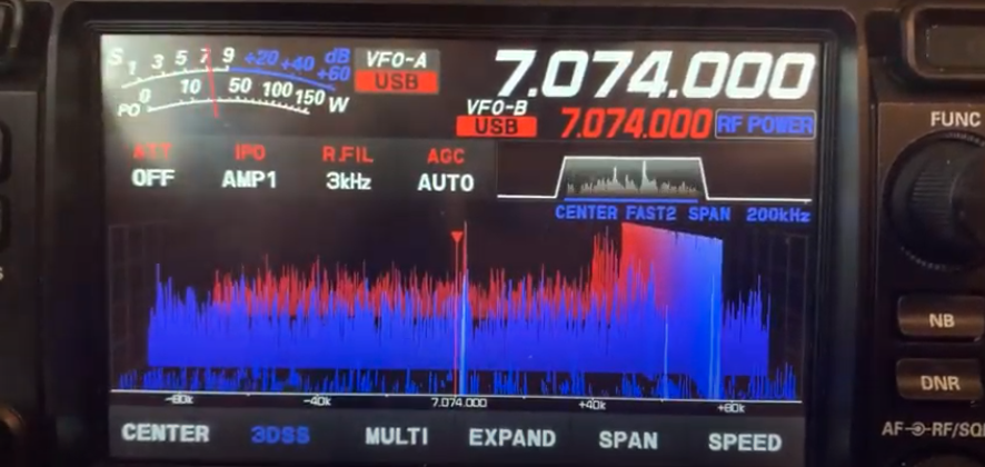
While setting up the FTDX10 with my prefered settings, and getting familar with the scope function, I noticed this odd QRM occuring.

I’d not seen it before on the FT-991, but I’m guessing it’s always been there considering how limited the FT-991’s scope is compared to the amazing SDR driven scope of this new radio.

I recorded a short video of the QRM. If anyone has ideas how to track this down and/or identify it, please let me know!

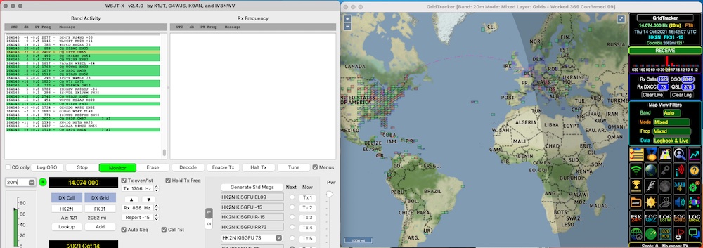
Out of the box, my FTDX-10 didn’t fully function with my existing WSJT-X setup I was using for the FT-991. Using some other videos as my guide, I’m re-configurating settings so they play nice with each other.

FTDX-10 SETTINGS:

FTDX-10 mode – set to DATA-U (data upper sideband):

Set the Attenuator, Preamp, Roof filter and AGC.

Changed the factory ‘REAR SELECT’, ‘RPORT GAIN’ and ‘RPTT SELECT’

Changed settings for ‘LCUT FREQ’, ‘LCUT SLOPE’, ‘HCUT FREQ’ and ‘DATA SHIFT (SSB)’ from factory as suggested by YTuber… he thought the default settings compromised signal quality, so I started with the same settings;

WSJT-X SETTINGS:

Opening the Settings dialog.

  • Set radio to ‘FTDX-10
  • Set serial port to your ‘Enhanced’ virtual port, mine is cu.SLAB_USBtoURAT
  • Set the baud rate to match the CAT Baud rate you set in FTDX-10 settings for me: 38400
  • Data Bits: Eight
  • Stop Bits: Two
  • Handshake: None (this was Hardware for my FT-991)
  • Force Control Lines: DTR: High RTS: High
  • PTT Method: CAT (this was RTS for my FT-991)
  • Mode: Data/Pkt (this was USB for my FT-991)
  • Split Operation: None (this was Rig for my FT-991 — I’ll probably set back to ‘Rig’ later)

Under the Audio settings… you’ll want to locate and select your USB Audio CODEC. This varies by platform.. this is on an older MacBook Pro with the Silicon Labs (SLAB) drivers installed.

Conclusion

These settings worked for me to get operational with WSJT-X on the FTDX-10.

It’s official – I’m a HAM!!

September 6, 2019 | Articles | No Comments

At 10:00 AM 29-AUG-2019, I finally did it.

The 1 hour drive into San Antonio was uneventful and not at all noteworthy.

Parking my car at the testing sight and walking into the test center was a completely different matter.

All the Elmers were nice enough, but all business with regards to getting the paperwork started, the tests handed out the administration. I’d studied hard for weeks, poured through Gordon West’s Technician’s class. In the end it all paid off with me missing just 1 of 35 questions on the test.

So it’s official.. no longer just a listener. It took just about 2 weeks for the FCC to post my ticket. I wasted little time applying for my state Amateur Operator auto license plate tags.

Now, time to charge up the Baofengs and start keying up!