In the quest to have the best shack I can have, I started the implementation of CMC chokes to mitigate noise in the transmission lines. I watched a lot of videos, read some blogs, and decided these basic objectives.
- Use a Type-31 toroid for HF operations. General knowledge indicates it’s good for 0-300MHz.
- Enclose in a watertight box with SO-239’s on each end to simplify most aspects of insertion into existing feedlines.
- Use as high a quality coax as I have on hand (in this case some RG8x).
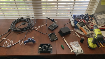
The choke was constructed to goal, and looks like this:

Testing the CMC in the real world, did more harm than good to the performance of my OCF80 wire antenna. The choke was places at the end of a 70′ RG58 feed, which passes through an Armitron RCS-4 switch, to 50′ of ABR RG8 to the house passthrough wall plate. From that plate to shack is 35′ of M&P Airborne 10.
After construction, I tested the box with my AA-35 and saw a less than impressive SWR impact with a 100w dummy load attached direct to the choke box.

In the real world, the insertion of the choke had the following impact on 20m performance of the OCF80.
| RG8 -> RCS-4 -> MP7 Flex -> CMC -> RG58 Feed -> OCF80 | SWR: 2.6 : 1 |
| RG8 -> RCS-4 -> RG58 Feed -> OCF80 | SWR: 1.8 : 1 |
| RG8 -> RG58 Feed -> OCF80 | SWR: 1.8 : 1 |
I was able to verify that the RCS-4 switch was not a factor in the SWR difference. The M&P 7 Ultraflex is a 6′ jumper between RCS-4 and the CMC box. I don’t suspect that, as it tests flat SWR into a dummy load.
Dumping all the graphs off of the AA-35, I see a very interesting patterns in the charts.


What is the question?
What did I do wrong here? Did I do something wrong?
I realize that all of the examples I looked at, used RG58 coax. Although the impedance is the same in the RG8x, perhaps the overall diameter, or shield type (it looks like it’s aluminum… grr) makes the suggested 12 turn construction incorrect.
Could and issue be in the way the toroid was wrapped? Most example are a simple circular wrap, but 1 example had a cross-over run at the 6 turn mark (making the 7th turn) that switches to opposite side of toroid, this making the 12th turn exist 180 degrees away from ‘insert’ point, instead of existing near insert point seen on a lot of other constructions.
I’ll probably take this one apart, wide another toroid I have with RG58 with not using the crossover, and see if that works better / different or worse.
I’m open to thoughts, ideas, corrections on this first attempt to build a choke.
cmc, common mode choke, HF, rg8x
